- 您现在的位置:买卖IC网 > Sheet目录3887 > PIC16F1825-E/ML (Microchip Technology)MCU PIC 14K FLASH 1K RAM 16QFN
132
ATmega8515(L)
2512K–AVR–01/10
be cleared, and SPIF in SPSR will become set. The user will then have to set MSTR to
re-enable SPI Master mode.
Bit 3 – CPOL: Clock Polarity
When this bit is written to one, SCK is high when idle. When CPOL is written to zero,
tionality is summarized below:
Bit 2 – CPHA: Clock Phase
The settings of the Clock Phase bit (CPHA) determine if data is sampled on the leading
The CPHA functionality is summarized below:
Bits 1, 0 – SPR1, SPR0: SPI Clock Rate Select 1 and 0
These two bits control the SCK rate of the device configured as a Master. SPR1 and
SPR0 have no effect on the Slave. The relationship between SCK and the Oscillator
Clock frequency f
osc is shown in the following table:
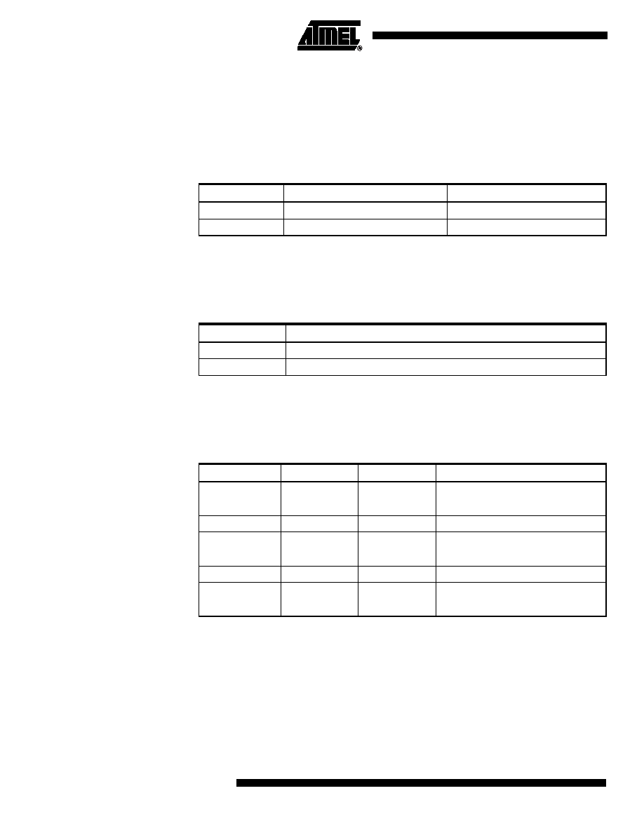
Table 56. CPOL Functionality
CPOL
Leading Edge
Trailing Edge
0
Rising
Falling
1
Falling
Rising
Table 57. CPHA Functionality
CPHA
Leading Edge
Trailing Edge
0
Sample
Setup
1
Setup
Sample
Table 58. Relationship Between SCK and the Oscillator Frequency
SPI2X
SPR1
SPR0
SCK Frequency
00
0
f
osc/4
00
1
f
osc/16
01
0
f
osc/64
01
1
f
osc/128
10
0
f
osc/2
10
1
f
osc/8
11
0
f
osc/32
11
1
f
osc/64
发布紧急采购,3分钟左右您将得到回复。
相关PDF资料
PIC16F1828-I/SO
IC PIC MCU 8BIT 14KB FLSH 20SOIC
PIC16F688-I/SL
IC PIC MCU FLASH 4KX14 14SOIC
22-02-3213
CONN FFC/FPC VERTICAL 21POS .100
22-15-3193
CONN FFC/FPC 19POS .100 RT ANG
PIC16C433T-E/SO
IC MCU CMOS 8BIT 10MHZ 2K 18SOIC
22-02-3103
CONN FFC/FPC VERTICAL 10POS .100
PIC16C432T-E/SS
IC MCU CMOS 8BIT 20MHZ 2K 20SSOP
PIC16C432-I/P
IC MCU CMOS 8-BIT 20MHZ 2K 20DIP
相关代理商/技术参数
PIC16F1825-E/ML
制造商:Microchip Technology Inc 功能描述:; Controller Family/Series:PIC16F; Core
PIC16F1825-E/P
功能描述:8位微控制器 -MCU 14KB FL 1KBRAM 32MHz 12I/0 Enhanced Mid RoHS:否 制造商:Silicon Labs 核心:8051 处理器系列:C8051F39x 数据总线宽度:8 bit 最大时钟频率:50 MHz 程序存储器大小:16 KB 数据 RAM 大小:1 KB 片上 ADC:Yes 工作电源电压:1.8 V to 3.6 V 工作温度范围:- 40 C to + 105 C 封装 / 箱体:QFN-20 安装风格:SMD/SMT
PIC16F1825-E/P
制造商:Microchip Technology Inc 功能描述:; Controller Family/Series:PIC16F; Core
PIC16F1825-E/SL
功能描述:8位微控制器 -MCU 14KB FL 1KBRAM 32MHz 12I/0 Enhanced Mid RoHS:否 制造商:Silicon Labs 核心:8051 处理器系列:C8051F39x 数据总线宽度:8 bit 最大时钟频率:50 MHz 程序存储器大小:16 KB 数据 RAM 大小:1 KB 片上 ADC:Yes 工作电源电压:1.8 V to 3.6 V 工作温度范围:- 40 C to + 105 C 封装 / 箱体:QFN-20 安装风格:SMD/SMT
PIC16F1825-E/SL
制造商:Microchip Technology Inc 功能描述:; Controller Family/Series:PIC16F; Core 制造商:Microchip Technology Inc 功能描述:IC, 8BIT MCU, PIC16F, 32MHz, SOIC-14
PIC16F1825-E/ST
功能描述:8位微控制器 -MCU 14KB FL 1KBRAM 32MHz 12I/0 Enhanced Mid RoHS:否 制造商:Silicon Labs 核心:8051 处理器系列:C8051F39x 数据总线宽度:8 bit 最大时钟频率:50 MHz 程序存储器大小:16 KB 数据 RAM 大小:1 KB 片上 ADC:Yes 工作电源电压:1.8 V to 3.6 V 工作温度范围:- 40 C to + 105 C 封装 / 箱体:QFN-20 安装风格:SMD/SMT
PIC16F1825-E/ST
制造商:Microchip Technology Inc 功能描述:; Controller Family/Series:PIC16F; Core 制造商:Microchip Technology Inc 功能描述:IC, 8BIT MCU, PIC16F, 32MHz, TSSOP-14
PIC16F1825-I/ML
功能描述:8位微控制器 -MCU 14KB FL 1KBRAM 32MHz 12I/0 Enhanced Mid RoHS:否 制造商:Silicon Labs 核心:8051 处理器系列:C8051F39x 数据总线宽度:8 bit 最大时钟频率:50 MHz 程序存储器大小:16 KB 数据 RAM 大小:1 KB 片上 ADC:Yes 工作电源电压:1.8 V to 3.6 V 工作温度范围:- 40 C to + 105 C 封装 / 箱体:QFN-20 安装风格:SMD/SMT